The CFB boiler of a power plant is an ultra-high pressure reheat, single drum natural circulation, island layout, all-steel frame suspended circulating fluidized bed boiler. It uses high temperature insulated cyclone separator for gas-solid separation. There are three volute insulated steel plate cyclone separators. The cyclone separator cylinder is made of 10mm carbon steel plate. A wear-resistant layer is laid on the flue gas side. Insulation material is laid between the steel plate and the wear-resistant layer. An annular support is set at the junction of the cylinder and cone of the cyclone separator and placed on the steel frame beam. A non-mechanical “U”-shaped return feeder is arranged at the bottom of each cyclone separator, and the material fluidization returns to the furnace through the return feeder leg. The return feeder leg and the return feeder are connected with non-metallic expansion joints. The boiler return feeder leg plays a vital role in the safe, stable and reliable operation of the unit. If the boiler return feeder leg is red and the refractory material enters the slag drop pipe to cause the return feeder leg to be blocked, the normal output of the boiler will be reduced at the least, affecting the load of the unit, and the boiler unit will not stop at the worst.
1. Problems with boiler return legs
The improper selection of the shell material of the expansion joint of the boiler return leg, insufficient reserved expansion gap, unreasonable structural form, and single anchor form have led to a high defect rate of refractory materials, frequent damage, and even caused the return leg shell to burn red, and the material to carbonize and fail, which seriously affected the safe operation of the unit, reduced the operating reliability of the unit, and directly affected the economic operation of the boiler.
(1) The original expansion joint inner tube was made of 16Mn steel, with an operating temperature of -20 to 475℃, and the operating temperature of the return leg was 800 to 900℃, which was higher than the operating temperature of 16Mn steel and could not adapt to the working conditions. Long-term over-temperature operation would eventually cause carbonization and failure of the material.
(2) The reserved expansion gap between the inner and outer tubes was insufficient, and the expansion was limited, causing local deformation of the expansion joint, resulting in the detachment of the refractory material.
(3) The original refractory material was supported by an annular bracket. When the annular bracket was thermally expanded, it was restrained by the inner tube and deformed downward. The refractory material could not be effectively supported and eventually fell off.
(4) The original anchors were Y pins, which were staggered every 150 mm. There was no steel grid at the end of the pins, which made it impossible for the refractory material to form a whole. When individual pins failed, the local refractory material would loosen, and there would be no reliable connection between adjacent refractory materials, which would eventually fall off.
2. Solutions for the falling off of refractory and wear-resistant materials of boiler return leg expansion joints
(I) Design and implementation of the scheme
The operating temperature of the boiler return leg is 800-900℃, and 16Mn steel cannot meet the operating conditions, which is the main reason for the damage of the return leg cylinder; the reserved gap between the inner and outer cylinders is insufficient, and the expansion is limited to produce large stress, causing local deformation of the inner cylinder wall, which is the main reason for the falling off of the refractory material; the unreasonable design of the refractory bracket and anchor is a secondary reason for the falling off of the refractory material.
Based on the above analysis, the solutions formulated in this paper are as follows:
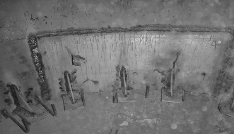
1. Replace the material of the inner cylinder of the expansion joint with 1Cr18Ni9Ti, reserve 50mm expansion margin, and weld the refractory bracket. The butt weld of the steel plate has a 30° groove, and the welding rod with model A302 and diameter of 3.2mm is selected. The welding current is 90-110A to ensure full penetration of the material thickness. The refractory bracket is changed from a ring to a 150mm×200mm×12mm steel plate dispersed support arrangement. The steel plate is made of 1Cr18Ni9Ti and reinforced with a triangular plate of the same material, which can not only avoid large stress deformation caused by thermal expansion of the ring plate, but also effectively support the refractory material; the bracket fillet welds are all fully welded, and the weld leg height is 10mm. The welded cylinder and bracket are shown in Figure 1.
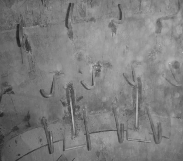
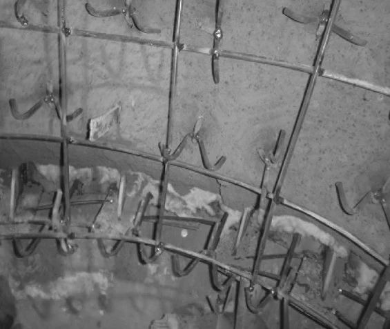
2. The anchor material is 310S, and 10mm×300mm pins are made. They are staggered every 100mm, fully welded at the root, and welded at the end with a 100mm×100mm steel mesh. A 3mm maze expansion joint is reserved every 500mm to meet the expansion requirements of refractory materials. The welding rod is A402, the welding current is 90~110A, the weld direction is fully welded, the anchor welding must be firm, there should be no cracks and slag inclusions, and it should be perpendicular to the guard plate. The surface is painted with 1~2mm thick asphalt paint. Before the construction of the thermal insulation castable, 2 layers of 20mm aluminum silicate fiberboard are pasted against the guard plate, and the layers are pasted with staggered seams. When constructing the thermal insulation castable, the manual laying method is adopted. During the construction, it must reach 148mm thick at one time. Do not construct in layers. Use special tools to pat it densely and then press it (air circulation is strictly prohibited around the pins), and the surrounding construction joints are patted densely. Weld 100mm×100mm steel mesh of 6mm and 310S material to enhance the fixation of wear-resistant castables. All nails should be painted with asphalt paint before plastic construction.
Welding pins are shown in Figure 2, and welding steel mesh is shown in Figure 3.
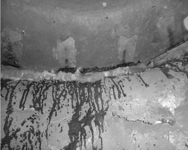
3. Wear-resistant plastic construction. After the plastic is laid on the construction component, use a wooden hammer or rubber hammer to pound it tightly. The joints between the blocks should also be pounded tightly to make the joints tight, and the surface should be smoothed and flattened. The joints between the construction site and the original wall should ensure a smooth transition, and no concave or convexity. Use aluminum phosphate solution to soak aluminum silicate fiberboard to seal the expansion joint to avoid air leakage during boiler operation, which may cause the non-metallic compensator to burn out. The expansion joint sealing after the wear-resistant plastic construction is completed is shown in Figure 4.
(II) Features of the solution
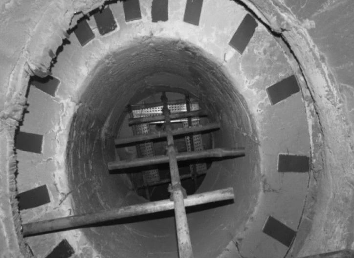
1. After adopting the above solution, the temperature of the expansion joint was measured after the boiler unit was started, and there was no over-temperature phenomenon. After the unit was shut down, there was no sign of shedding, and the expected goal was achieved. After the boiler unit has been running for 2 years, the refractory and wear-resistant materials of the return leg expansion joint have no defects such as shedding, cracking, and deformation, as shown in Figure 5.
2. After successfully transforming one of the boilers using the above scheme, the same transformation was carried out on the other three boilers, with good results. So far, the refractory material at the expansion joint of the return leg is in good condition, and there has been no overheating of the cylinder or refractory material shedding.
3. Through transformation and management, the reliability of the return leg is effectively improved, ensuring the safe and stable operation of the unit; reducing the cross-operation of furnace maintenance and reducing the safety risk of maintenance; reducing maintenance items, reducing maintenance costs, and shortening the maintenance period.
III. Conclusion
This paper optimizes the refractory material part of the expansion joint of the return leg of the CFB boiler unit accordingly, avoiding the problem of refractory material shedding caused by low material grade, insufficient expansion gap, low anchor strength, etc., improving the reliability of the return leg, ensuring the safe and stable operation of the unit, reducing the cross-operation items of furnace maintenance, and reducing the safety risk of maintenance.

