Due to the different parts of circulating fluidized bed boilers, the construction process is different, and the construction process of different refractory and wear-resistant materials is also different. The following is the construction process of refractory and wear-resistant materials for a domestic 300MW circulating fluidized bed boiler:
1. Construction process of wear-resistant materials in the combustion chamber
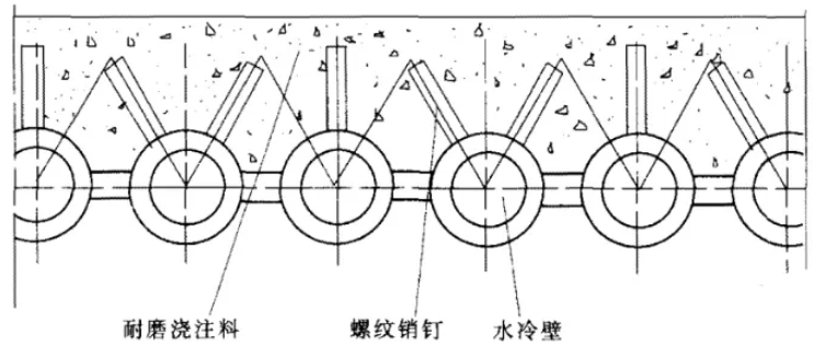
As shown in Figure 1, this is the construction process of wear-resistant castables on the water-cooled wall tubes in the lower part of the combustion chamber of the circulating fluidized bed boiler. The wear-resistant materials are fixed by metal pins welded on the surface of the tube. Since this area is the dense phase area in the lower part of the combustion chamber, its material concentration is very high, and the mixing and turbulent flow are very strong, so the wear is very serious. In order to prevent wear, a certain thickness of refractory and wear-resistant castables must be lined in the lower dense phase area.
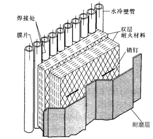
The area where wear-resistant castables need to be laid is also the lower part of the wing wall tubular water-cooled wall, especially where the tube passes through the wall, because the wear in this area is quite serious. As shown in Figure 2, for special areas with thick refractory materials in the furnace, the refractory materials need to be poured in layers.
2. Construction technology of wear-resistant materials inside the return device
The construction technology of wear-resistant materials inside the return device mainly adopts the structural form of wear-resistant materials and thermal insulation materials. There are several basic types:
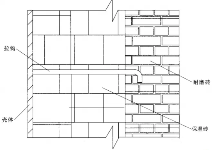
(1) Wear-resistant brick lining + thermal insulation brick type
In order to solve the expansion, expansion joints are left at certain intervals, that is, a 2mm mortar joint is left between the wear-resistant bricks. In addition, in order to transfer the mass of the wear-resistant bricks to the steel shell in layers, a high-temperature heat-resistant steel bracket is provided at an appropriate height.
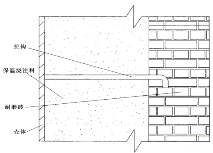
(2) Wear-resistant brick + thermal insulation castable type
In order to solve the expansion, expansion joints are left at certain intervals, that is, a 2mm mortar joint is also left between the wear-resistant bricks. Similarly, brick brackets are set at certain heights for layered unloading. This type is suitable for steel shells with complex shapes and other parts that are not suitable for thermal insulation bricks.
(3) Wear-resistant castable + thermal insulation castable type
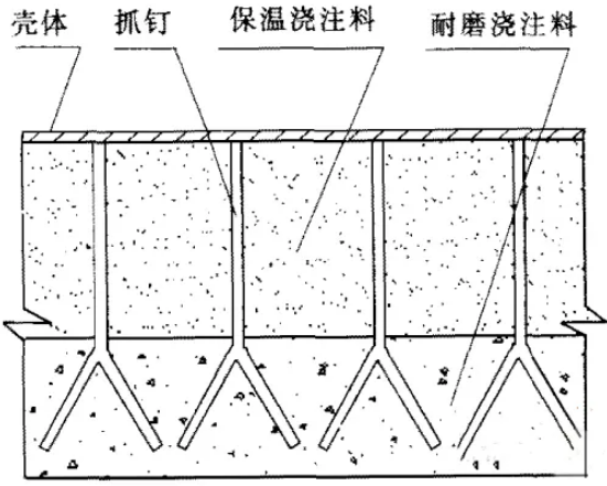
As shown in Figure 3, this is a wear-resistant castable + thermal insulation castable type. This structural type arranges “Y”-shaped grippers according to a certain rule to fix the wear-resistant lining. In order to solve the temperature expansion difference between the metal grippers and the wear-resistant castable, the grippers should be coated with 1mm thick asphalt to avoid the cracking of the refractory material due to the different expansion of the metal pins and the refractory material under hot conditions. At the same time, the wear-resistant castable needs to add stainless steel fiber at a ratio of 2%, and the wear-resistant lining should also have appropriate expansion joints.
3. Construction process of anti-wear materials inside the separator
Since the separator is a key component in the circulating fluidized bed boiler, the following anti-wear design structures are mainly used for the high-temperature adiabatic separator:
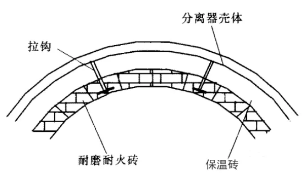
(1) Wear-resistant brick lining + insulation brick type
As shown in Figure 4, it is a wear-resistant brick lining + insulation brick type. In order to solve the expansion, expansion joints are left at certain intervals, that is, a 2mm mortar joint is left between the wear-resistant bricks. The wear-resistant bricks are reinforced by hooks welded on the steel shell. In order to transfer the mass of the wear-resistant bricks to the steel shell in layers, a high-temperature heat-resistant steel bracket is provided at an appropriate height. This type is suitable for large-area flat or arc surfaces.
(2) Wear-resistant brick + thermal insulation castable form
As shown in Figure 5, it is a wear-resistant brick + thermal insulation castable form. In order to solve the expansion problem, expansion joints are left at certain intervals, that is, a 2mm mortar joint is left between the wear-resistant bricks. There are grooves on the wear-resistant bricks for hook fixation. In addition, in order to transfer the mass of the wear-resistant bricks to the steel shell in layers, a high-temperature heat-resistant steel bracket is provided at an appropriate height. This form is suitable for steel shells with complex shapes and other parts that are not suitable for thermal insulation bricks.
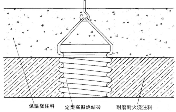
(3) Castable structure using fixed gripping nails and high-temperature sintered bricks
As shown in Figure 6, this is a castable structure using fixed gripping nails and high-temperature sintered bricks. In locations where wear-resistant refractory bricks are difficult to construct, wear-resistant refractory castables are generally used to achieve anti-wear design. Since the curing process of the castable must be carried out after installation in the separator, the wear resistance of the castable is lower than that of wear-resistant refractory bricks due to environmental and heating conditions. Steel fibers should be added to the castable, and the gripping nail density should be appropriately increased.
(4) Layered hook brick structure
As shown in Figure 7, this is a layered hook brick structure. The cylindrical part and the conical part of the separator both adopt a wedge-shaped wear-resistant brick and a hook brick. This structure can effectively prevent the wear-resistant refractory bricks from falling off, making it almost impossible for any independent wear-resistant refractory brick to fall off.
(5) Hook wedge brick structure
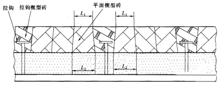
As shown in Figure 8, this is a hook wedge brick structure. The angle of the wedge hook brick is used to make the L1 of the flat wedge brick between the two wedge hook bricks smaller than L2, making it difficult to disengage and ensuring safe operation. It is mainly used in the cylindrical part and cone section of the separator.
4. Matters to be noted when constructing refractory and wear-resistant materials
(1) All metal and castable contact surfaces should be painted with asphalt or wrapped with ceramic fiber paper.
(2) The gaps between the hook grooves of the hook bricks should be filled with mortar.
(3) The mortar joints between all wear-resistant refractory bricks should be less than 2mm.
(4) The mortar between each wear-resistant refractory brick should be filled without leaving any gaps, otherwise the flue gas will enter through the gaps during boiler operation, aggravating the erosion or peeling of the wear-resistant refractory lining.
(5) In principle, when laying wear-resistant refractory bricks, do not cut them. If cutting is necessary, each brick should not be less than 1/2. If this is not possible, two bricks can be cut at the same time.
(6) All bricks from bottom to top close to the push plate have hooks. On all support plates, the next layer of bricks should be long bricks with expansion joints to form an overall stable furnace wall.
(7) All mortar joints between bricks should be coated with refractory mortar, and all bricks should be laid along the joints. If the corners or end faces of the bricks are broken or cracked, they should be replaced.
(8) When laying bricks, use a rubber hammer or a wooden hammer to tap gently to make the bricks tightly combined. Do not use an iron hammer.
(9) When constructing wear-resistant and refractory castables, the amount of water added should be strictly controlled. The general amount of water added is 6-8%. The stirring must be uniform. The water quality used should be clean, and its pH value should be between 6 and 8. The chloride ion content should not exceed 150ppm. It is strictly forbidden to use water that exceeds the standard and water with suspended matter.
(10) The tools used in the construction process of castables must be clean and not contaminated, especially to avoid chemical contamination.
(11) During construction, the castable should be formed with a vibrator and vibrated evenly. The vibrator rod should be slowly pulled out during vibration to avoid creating cavities in the castable.
(12) After demolding, the density of the castable should be checked. You can tap it lightly with a hammer. If a crisp echo is heard, it means that the castable is relatively dense. At the same time, honeycombs and rough surfaces should not appear. If the area of honeycombs and rough surfaces is large, they should be partially chiseled off and re-constructed.
(13) After the mold is inspected and qualified, the wear-resistant and refractory castable lining can be baked after 5 to 7 days of normal temperature curing.

